Hardware progress continues well, we've a few small updates here and a few nice GIFs.
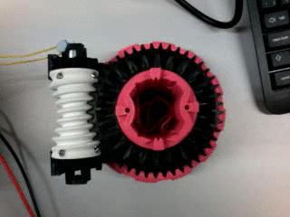
Firstly the worm gears, these are used as a non-backdrivable reduction gear connecting the motors which power the hinge to the bevel gears within the 2 Degree of Freedom hinge system. The gear teeth give a good fit into the worm and boost the torque by about 45:1. An array of microswitches monitor the motions of the hinge by being tapped by strategically placed notches on the gears themselves and elsewhere around the hinge. Efforts are being made to ensure a particularly good accuracy for the centred and +/- 90
° positions.
 |
| Worm gear in operation, on a complete robot the angle which the camera is viewing from will be towards the centre of the robot and obscured by the Raspberry Pi and other central components. The arms of the hinge are not fitted in this image. |
 |
| Approximately half a robot, assembled. Docking port 1 is on the left in this image with (white) docking spikes fitted, port 3 fits on at the right hand end. Worm gears (in white and black) are visible towards the back and infront of them are the gears (both black) which interlock with the worms. The white parts in the centre are a section of the hinge arms. The centre, which will sit between the (pink) ends of the wheel 1 and wheel 3 mounts, has now been designed but has yet to be printed as it is a long job (about 10 hours). The elevating docking port (port 4) is towards the camera in this image. |
Secondly, the first version of the docking port printed circuit board has now been fabricated. This is a much neater more compact equivalent of the same circuits used in the TAROS demo devices. The board circuitry and the microcontroller within it monitor for 38KHz byte communications between robots, as well as sending similar messages outward at intervals defined by a variable controleld from the central Raspberry Pi computer. This board is also responsible for detecting 5KHz guidance cones for docking, controlling the docking hooks and providing H bridge circuits for the wheel behind the port. Testing begins next week.
 |
| The docking board PCB, one of 4 such PCBs on an Omni-Pi-tent module. |


No comments:
Post a Comment
Thank you for your thoughts, your comment should be visible soon.