You may remember that in the videos uploaded with the last post multiple robots may crash into one another and try to wrestle for dominance when they both are trying to be recruited to the same port. this was especially visible in the video with the moving seed robot. This has now been fixed by adding in a non-conflict docking strategy, the previous self-assembly method is unchanged except that now the first robot to acknowledge a recruiting cone gets priority to try to dock within it. See the video for this in operation.
With the non-conflict code aded to the robot controllers this self-assembly strategy appears to be equivalent to Liu and Winfield's [Distributed autonomous morphogenesis in a self-assembling robotic system, Morphogenetic Engineering: Understanding Complex Systems, 2012], all differences in performance and speed being assumed due to the "hardware" differences between our simulated Omni-Pi-tent units and the simulated 2D simplified SYMBRION units of their work.
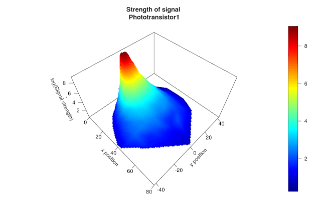
Another major item of progress has been in taking a series of precise measurements of signal strength for the 5KHz infrared docking signal, a mathematical model was fitted to this data and it is now in use within the next iteration of V-REP simulations. This was performed by positionong an emitting port at one location then moving a receiving port around and recording signal strengths, after op amp and software filtering and amplification, at positions across a 2D grid. The TAROS demo devices were used for the emitting and receiving ports, after some minor repairs to fix the damage which had limited the demo's range at TAROS. Our simulated robots are now getting their simulated sensor data based on measurements of what real robots will gather.
*Later these will be able to be modified very quickly into self-repair strategies

No comments:
Post a Comment
Thank you for your thoughts, your comment should be visible soon.